Inhaltsverzeichnis
VGA: Vector Graphics Adapter
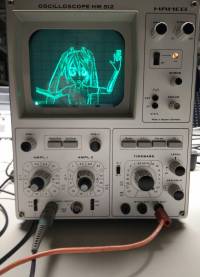
Using an Oscilloscope for Vector graphcis is propably an idea as old as the X/Y-Mode. Apart from Lissajous-Curves, the PC soundcard has become a popular method for drawing vector graphics on oscilloscopes. Left and right channel of the soundcard are connected to the x and y inputs of the scope to drive the electron beam.
While a sound card is essentially a digital to analog converter, it also includes low pass filters and coupling capacitors for removing the DC part of the signal. This improve the audio quality and save your speakers from harmful DC. Howerver, for our purpose these are harmful because the low pass filter limits the speed at which the beam can move and the loss of the DC offset makes the animation whobble around on the screen. The animation must be carefully designed to work around these limitations.
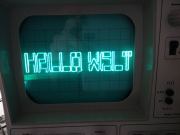
The solution comes from the other digital to analog converter still commonly found on modern PCs: The VGA-Port. While it may be intended to drive raster screens, it essentially a 3 Channel, High-speed (> 100MHz) DAC. Using 2 of these channels (Red and Green) the electron beam of an Oscolloscop can be driven in X and Y directions much like the soundcard method, but much faster and without the harmful filter stages. This makes it almost ideal for drawing vector graphics on a scope.
Hardware
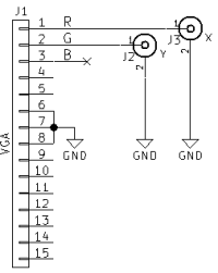
- Connect VGA Pin 1 (red) to the horizontal input of the scope (often channel 2)
- Connect VGA Pin 2 (green) to the vertical input of the scope (often channel 1)
- Connect the grounds of PC and oscilloscope.
Software operation
- The vectorization is implemented as a set of mpv video filters.
- I made a fork of mpv which contains these filters.
- The input video (or image) is passed through the Canny edge detector
- The edgedetect filter from ffmpeg/libavfilter is used (-vf lavfi=edgedetect) to extract edges from the image.
- Following the edge detection a second filter is used to extract the contours from the image. The FindContours function from openCV takes the image and extracts its contours as paths of vectors (–vf vector).
- The vector filter also iterates over these paths to create a „vector image“. In this image the red and green color channels of each pixel contain the coordinates of the edge path vectors.
- The available „pixels“ of the vector image are distributed among the vectors to draw by writing the same value multiple times. This ensures the entire image and thus VGA scanout time is used.
- The ffmpeg edgedetect filter provides an intensity value in its output depending on how sharp an edge is.
- This is used to give more vector image „pixels“ to more prominent edges to make them brighter on the scope output.
- Less prominent edges get less scanout time and will appear dimmer because the electron beam moves over these spots more quickly.
- This method works without the use of a dedicated intensity (Z) input on the oscilloscope.
- A problem of using the VGA port is the blanking periods during which the VGA Port will output 0 volts on all channels and thus move the electron beam to the lower left corner of the scope screen.
- A bright dot appears there and can potentially damage the phosphor coating of the CRT. It should be moved outside the visible area using the horizontal/vertical controls of the scope.
Usage
- To reduce blanking periods a „wide“ video mode should be used (e.g. 2048×200@60):
xrandr --newmode scope 26.7  2048 2049 2060 2060 200 200 216 216 +hsync +vsync
xrandr --addmode VGA1 scope
xrandr --output VGA1 --mode scope --right-of <PRIMARY-MONITOR>
- ffmpeg is needed
- opencv3 is also needed
- The modified mpv media player with the custom filters can retrived with
git clone https://gitlab.warpzone.ms/da1l6/vga.git - Example usage command:
/path/to/build/mpv --fs --geometry=<WIDTH-PRIMARY-MONITOR>:0 --loop --vf scale=576:512,lavfi=[edgedetect=high=0.04:low=0.03],vector:width=2048:height=200 <VIDEO>
- The optimal values for low and high can depend on video source. Just try a few.
- The canny edge detection is a CPU hog. Because of this
–vf scale:w:his used to scale down the image before running it.
Cheating at Vector Graphics - Displaying a Raster image
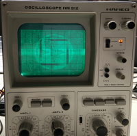
The trick of changing the brightness of vector paths can be used to display raster images.
The X and Y coordinates (red and green color channels) are counted upwards to make the beam scan the screen line by line, similar to a regular CRT monitor or TV.
The brightness is reproduced by changing the scan speed. Bright areas get more pixels of the vector image and thus appear brighter. Dark areas are assigned less pixels, thus are scanned out more quickly.
Usage
/path/to/build/mpv --fs --geometry=<PRIMARY-MONITOR-WIDTH>:0 --loop --vf scale=256:256,vectorraster:width=2048:height=300 <VIDEO>
Screen Capture
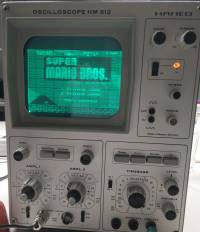 mpv can capture the screen contents with the help of ffmpeg. This way it is possible to show screen contents (e.g. Games) on the oscilloscope screen.
This works with both raster and pure vector mode. The Image on the right is made using raster mode.
/path/to/build/mpv av://x11grab::0 --demuxer-lavf-o='video_size=<WIDTH>x<HEIGHT>,grab_y=<XPOS>,grab_x=<YPOS>,framerate=30' ...
Video input devices like TV, Webcams and more can be accessed as well:
/path/to/build/mpv tv:// ...
Digital oscilloscopes
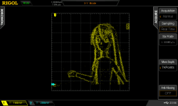
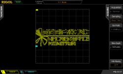
If you don't have access to an old-school analog oscilloscope, a modern DSO can also be used, but the image quality is poor in comparison. The raster image mode is barely useable.
The reason for this is that DSOs use samplig (periodically measuring the input signal). Whatever is measured at the sample time is painted on the screen as a dot. All dots drawn have the same brightness and the sampling is not synchronized with the VGA „pixel“ output clock.
This causes a lot of samples taken in between actual the points of image, making the display very noisy.
DSO Tips:
- Use a high VGA refresh rate (e.g. 120Hz) to increase the pixel clock and reduce the time „in between“ points.
- Use a wide mode with few H-Blanks (always good).
- Use a low memory depth (e.g. ~7kPoints).
- Try adjust the DSO sample rate to find the spot of minimal noise.
